
Missing and double solder balls in an automatic BGA reballing machine should be investigated at the stage where they first appear. A vacant location before reflow suggests a placement or retention problem; a location that becomes defective afterward introduces wetting, heating or movement as additional possibilities. Changing feed and reflow settings together obscures that distinction.
Start with identified balls, matching tooling and a correctly supported package. Then inspect the array before and after attachment. An automatic reballing machine can repeat a good setup or repeat a bad one; fault correction depends on a clear defect map and controlled trials rather than indiscriminate increases in feeding action.
Missing balls can result from incomplete delivery, blocked openings, poor package alignment or loss during transfer. Double balls can arise when excess material remains at a location, when tooling does not restrict occupancy as intended, or when balls move and collect together. The relevant mechanisms depend on the machine architecture.
First define what “double” means in the inspection result. Two loose spheres at one site are different from one oversized attached feature after reflow. The latter may indicate merged material or excess solder volume and needs to be traced back through the earlier checks.
Map each defect to the package coordinate and record when it is detected. A repeatable missing site suggests a local feature worth inspecting; a broad random pattern points toward a different set of causes. Neither pattern alone proves the root cause, but both help prioritize observations.
Check incoming material and package readiness before altering the recipe. Wrong sphere diameter, mixed sizes, contaminated surfaces or a damaged land can undermine otherwise correct machine settings. A feeding change cannot make an incompatible ball or missing wettable surface acceptable.
Keep the package and tooling identity with the image record. Without that information, a defect photo from one package variant can be misinterpreted as evidence about another. Preserve the last known good setup so corrective trials have a meaningful comparison.
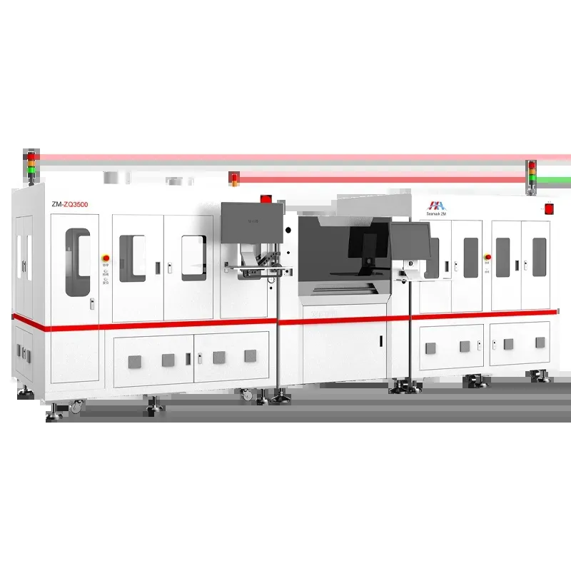
Confirm how the machine delivers and retains balls. A system that distributes spheres through a mask has different variables from equipment that places them individually. Apply only the adjustments relevant to the installed mechanism and approved operating instructions.
Inspect the material path for contamination, accumulation and signs of inconsistent transfer. Where the system uses vacuum or pressure, check the required supply conditions, connections and working surfaces. Where motion or agitation distributes balls, verify the programmed action and actual mechanical condition before increasing it.
Control the amount of material supplied to the process. Too little can leave parts of an array unfilled; excessive material can make removal of surplus balls less consistent. Establish the operating range through trials rather than assuming that a fuller reservoir always improves the result.
Flux can influence retention and release. Too little, excessive or uneven application can change how spheres remain on the package or tooling. Use the specified material and quantity, and assess its condition over the actual working interval rather than only at the start of the shift.
A BGA reballing machine evaluation should use the intended package, sphere lot and tooling. Ask to inspect placement before reflow as well as the finished array, so the feeding capability is assessed separately from the thermal attachment process.
A blocked aperture is a local restriction. It may retain residue or debris that prevents normal sphere passage or seating. Clean and inspect the opening with the prescribed method, then check for damage; forcing a tool through it can alter the geometry and create a new defect.
Misalignment shifts the relationship between the array and tooling. It can produce a repeated offset or failures over a region, especially if the package is rotated, the wrong datum is used or the fixture does not seat consistently. Verify the full pattern, not only one apparently aligned corner.
Thermal expansion and package variation can complicate a setup that appears correct while cold. If defects appear only after warming or repeated cycling, examine fixture movement and tooling behavior under those conditions. Do not assume an initial alignment photograph represents the entire cycle.
Observed pattern | First investigation | Avoid assuming |
Same isolated site repeatedly empty | Aperture condition and underlying land | More feed will clear it |
Array shows a consistent offset | Datum, orientation and fixture seating | Every opening is blocked |
Defects change after transfer | Retention and mechanical movement | Initial filling was incomplete |
Defects arise only after reflow | Wetting, material and thermal response | Feeding is necessarily at fault |
If a cleaned opening continues to fail at the same package coordinate, inspect the package as well as the tool. An absent or contaminated land can mimic a placement problem at final inspection. A useful investigation follows the material through the sequence instead of repeatedly correcting the most visible machine setting.
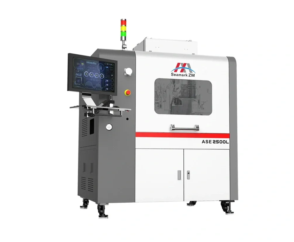
Inspect the array immediately after placement and again after reflow and cooling. Use images with enough resolution and a consistent orientation to compare the same locations. This simple separation identifies whether a sphere was absent at delivery or became unacceptable later.
A sphere present before reflow may fail to attach because of surface condition, incompatible flux or an unsuitable thermal cycle. Movement can occur before the material becomes securely attached. These mechanisms require different corrections from a feeder that never delivered the sphere.
Likewise, an irregular attached feature should not automatically be labeled a double feed. Check the pre-reflow image and the material condition. Residual solder volume, merged spheres and uneven wetting can produce different final shapes that look similar in a single inspection view.
Validate the thermal process using measurements appropriate to the package. Heater setpoints do not directly establish the conditions at the attachment surface. Repeatedly increasing temperature to improve appearance can expose the component to unnecessary thermal stress while leaving the actual cause unresolved.
Machine vision needs its own verification. Challenge detection with representative missing, extra and abnormal features where the process allows. A pass signal is meaningful only within the demonstrated ability of the inspection configuration. Top-down occupancy checks also do not establish coplanarity or internal component health.
Make a targeted change with a recorded reason, then repeat the relevant observations. For example, if a local aperture restriction is found and corrected, inspect filling at that coordinate before reviewing the final attached array. Do not simultaneously alter feed action, alignment and reflow unless the trial is explicitly designed to assess their interaction.
Use a representative trial quantity agreed for the process and consequence of failure. One clean array confirms one result; it does not establish sustained performance over a production run. Include conditions such as restart, replenishment or tool cleaning where they are relevant to the defect history.
Record the approved setup with the package identity, ball diameter and alloy, tooling revision, fixture, flux and program version. Include inspection results and any required moisture or thermal-history records. Those inputs make a later recurrence comparable with the released condition.
Before restarting production, deal with material made since the last known acceptable checkpoint. Determine what requires reinspection, reprocessing or rejection through the product's quality process. Correcting the machine does not retrospectively establish that earlier output is acceptable.
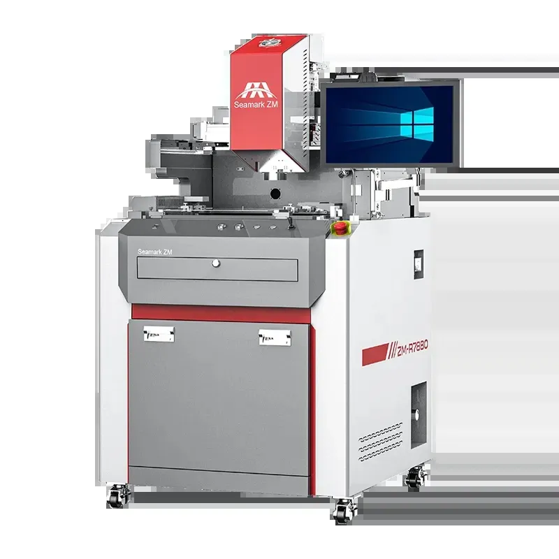
After the reballed package passes inspection, install it using a rework system with a validated board-attachment process. A package with a complete array still needs acceptable geometry, appropriate handling and a suitable installation process. Final electrical and functional testing evaluates the repaired assembly beyond the placement machine's inspection scope.
Only when evidence points to inadequate delivery and the adjustment is within the machine's process guidance. Blocked tooling, misalignment or an unacceptable land require different actions.
The final appearance may result from movement, merging or excess solder rather than an obvious double placement. Compare pre-reflow images with the same coordinates after attachment.
No. Ball map, diameter, package geometry and datum arrangement also matter. Confirm the complete tooling match before using it.
It demonstrates a single acceptable result. Release should use the agreed validation scope, relevant operating conditions and inspection criteria for the intended production process.
Troubleshoot an automatic BGA reballing machine by locating the first point of failure. Separate delivery and alignment from retention and thermal formation, make targeted adjustments, and verify sustained results. Maintain traceable setup and inspection records so the corrected process can be repeated and its output released appropriately.
· IPC-7711C/7721C: Rework, Modification and Repair of Electronic Assemblies (Table of Contents)
· NASA: Lead-Free Solder Body of Knowledge, Appendices (2005)
 EN
 es
 ko
 de
 it
 pt
 th
 ar
 pl
 vi
 tr
 ru