
A controlled reballing process starts with the package specification, not with the stencil that happens to be available. Ball diameter determines solder volume, pitch defines the spacing between locations, and alloy influences reflow behavior and the final joint system. These values are related, but none can be substituted for another.
First confirm that the component is suitable and authorized for reuse. Reballing replaces external interconnect material; it does not repair a defective die or reverse internal package damage. A BGA reballing machine can support controlled processing, but the package drawing, material identity and inspection plan remain the basis for selecting the job parameters.
Use the exact component identity and package variant to obtain the ball map, dimensions and material requirements. Similar-looking packages can have different populated locations, ball sizes or special features. A stencil labeled only with a broad package family may not uniquely match the device.
Inspect a recovered BGA component before ordering balls. Check the substrate, lands and edges for damage, and review the removal and cleaning history. If the package is cracked, a land is missing or contamination cannot be removed through an acceptable process, choosing new balls does not resolve the underlying defect.
Do not infer original ball size from a flattened solder joint removed from a PCB. The original sphere changes shape during attachment, and residual solder may remain on both interfaces after separation. Use supplier data or a qualified characterization route rather than measuring a torn remnant as though it were an unused sphere.
Trace the ball material to its container and lot. An unlabeled supply with a familiar appearance is not sufficient evidence of alloy or diameter. Keep mixed or suspect material out of the feeder and record the consumables used for each released batch.
Some component suppliers do not support reuse of removed devices. Check that restriction and the product's repair requirements before developing a reball route. A physically successful operation can still be unsuitable for an application that requires new replacement components.

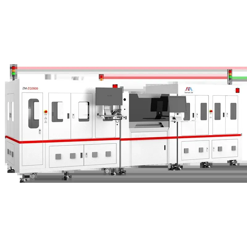
Pitch is the center-to-center distance between adjacent locations. Ball diameter is the size of a solder sphere before attachment. A package with a given pitch does not automatically require one universal ball diameter, because pad geometry and the intended interconnect structure also matter.
Read the drawing notes as carefully as the outline dimensions. Confirm whether a listed measurement describes an unattached ball, a finished package feature or a tolerance after processing. Check the ball count and depopulated areas rather than assuming every grid intersection contains an interconnect.
Sphere volume changes with the cube of diameter. As an illustrative calculation, increasing a sphere from 0.40 mm to 0.45 mm increases its volume by approximately 42%, even though the diameter changes by only 0.05 mm. These example dimensions are not package recommendations; they show why a visually small substitution can materially change solder volume.
Parameter | What it describes | Why confusion matters |
Ball diameter | Sphere size before attachment | Changes solder volume |
Pitch | Spacing between location centers | Controls array and tooling alignment |
Land diameter | Wettable attachment geometry | Influences the formed joint shape |
Ball map | Populated and empty positions | Prevents incorrect array population |
If the necessary drawing is unavailable, do not select balls solely from a generic pitch chart. Obtain the missing package data or use an approved engineering qualification route. Measuring a known good unused reference may provide useful evidence, but it should be part of a documented method rather than an informal guess.
Match alloy selection to the component, the PCB attachment process and the application's material requirements. Changing from one alloy system to another can alter the required thermal cycle, metallurgical interactions and final reliability. A lower melting temperature alone is not sufficient justification for conversion.
Residual solder is part of the material system. New spheres placed onto a surface carrying a different residual alloy may produce a mixed composition during reflow. The significance depends on the materials and process; a clean-looking package does not establish that the intended composition has been achieved.
Define how the original solder will be removed and what residual condition is acceptable. Avoid aggressive removal that sacrifices the land or metallization merely to obtain a visually bare surface. Material conversion, where permitted, needs an established method and verification appropriate to the product.
Select flux for compatibility with the alloy, package surfaces and cleaning route. Its task is to support wetting and attachment under the defined conditions, not to compensate for oxidized or damaged lands. Control its quantity and handling so it supports consistent placement and reflow.
Record the complete thermal history, including removal, cleaning-related heating, ball attachment and later PCB installation. An automatic reballing machine can improve repeatability within its capabilities, but automation does not make repeated thermal exposure irrelevant.
A ball-placement stencil or mask must match the array, sphere dimensions and placement method. Do not confuse it with a solder-paste printing stencil: their material-transfer functions differ, and aperture guidance for one cannot automatically be applied to the other.
Check the fixture orientation and datum before loading material. Package edges, markings and pin-one identification should agree with the job definition. A symmetric outline can make an incorrectly rotated component appear aligned until the populated pattern is examined.
Inspect apertures for contamination, damage and dimensional consistency. A partially blocked opening can cause a repeatable missing-ball location, while poor seating or unsuitable clearance can allow unintended balls to remain. Increasing feed action is unlikely to correct a damaged or mismatched mask.
After placement, verify the populated pattern before reflow. Check for missing, extra and doubled balls, including locations near edges and intentionally empty regions. If the process uses machine vision, review its actual ability to distinguish these conditions rather than relying on an overall pass signal alone.
Seamark's equipment range includes automated solder-ball placement and rework solutions. Select the relevant configuration through a trial with the package, tooling and acceptance criteria intended for production, rather than assuming that every machine uses the same feeding or attachment method.
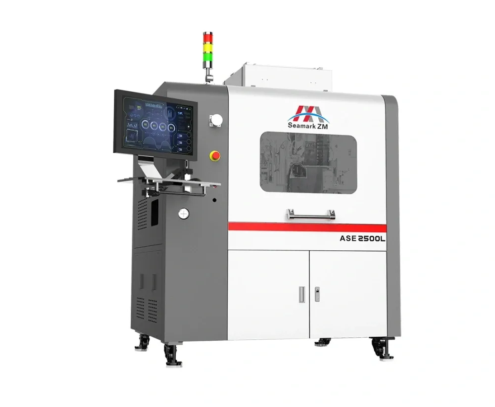
After reflow, the attached ball shape reflects solder volume, wetting and land geometry. Similar ball diameters before processing do not guarantee identical attached heights if surface condition or heating varies across the package.
Inspect the cooled package using a measurement method capable of evaluating the specified features. A top-down image can establish occupancy and some shape defects, but it does not directly measure every ball's height. Coplanarity assessment requires a suitable datum and measurement arrangement.
Look for unattached balls, bridging, displaced balls and unusual shape or size variation. Distinguish the geometry of the ball array from package substrate warpage, while recognizing that both can affect subsequent board attachment. Do not force a warped package flat simply to obtain a favorable inspection result.
A consistent-looking array still needs to be judged against the applicable package and process criteria. There is no universal visual threshold that fits every pitch and package construction. Where needed, qualification work may include more detailed analysis or mechanical evaluation of representative samples.
Before reinstalling the component during BGA rework, complete the required package inspection, cleaning and moisture-control steps. Reballing is one stage in the repair route, not proof that the original fault has been corrected.
No. Diameter describes the sphere; pitch describes spacing between locations. Use the package specification to establish both rather than treating them as interchangeable.
Not without engineering assessment. Larger spheres change solder volume and final geometry and may create bridging or other problems. First investigate the specified ball size, warpage and site condition.
Only through an authorized and qualified material-conversion route where the application permits it. Consider residual alloy, process compatibility and product requirements before making the change.
No. Reballing addresses external interconnects. The package still requires the inspections and electrical evaluation appropriate to its condition and intended reuse.
Select the reballing process from exact package data and an approved reuse decision. Treat diameter, pitch, alloy and tooling as separate controlled inputs, then inspect the attached array for occupancy, geometry and coplanarity. Release the component for installation only after the complete preparation and verification route is satisfied.
· IPC-7711C/7721C: Rework, Modification and Repair of Electronic Assemblies (Table of Contents)
· NASA / Jet Propulsion Laboratory: NASA Guidelines for BGA and DSBGA Selection and Application
· NASA: Lead-Free Solder Body of Knowledge, Appendices (2005)
 EN
 es
 ko
 de
 it
 pt
 th
 ar
 pl
 vi
 tr
 ru