
BGA rework equipment can process some shielded assemblies successfully, but only when access, heat flow and restoration of the shielding are planned together. A metal shield may block the nozzle or pickup head, conduct heat into neighboring areas, and hide parts that need inspection. Removing the BGA without accounting for those effects leaves important work unfinished.
Start by determining whether the shield has a removable lid, a soldered frame, or a one-piece soldered can. Then review the complete sequence from shield opening through final testing. The appropriate BGA rework equipment must accommodate the assembly in the configuration actually used during each operation.
Some can, provided the shield construction and surrounding assembly allow a controlled process. Others have access or thermal restrictions that make replacement of a larger module more practical. The decision depends on the physical design and required verification, rather than the shield's appearance alone.
Review drawings and inspect the board before applying heat. Identify clips, soldered seams, frame attachments, grounding contacts and nearby mechanical constraints. A lid designed to unclip is different from a shield whose perimeter is soldered to a large ground connection.
Also confirm the fault location. A malfunction inside a shielded area does not necessarily originate at the BGA. Power delivery, connectors and small surrounding components can produce related symptoms. Establish a diagnostic basis before opening a region that may require substantial restoration work.
Disconnect the assembly from power and follow its preparation requirements. Remove incompatible accessories or energy sources through the appropriate service procedure. Photograph shield orientation and contact details so the final configuration can be restored accurately.
Success means more than reaching the target chip. The repair plan must preserve nearby components, avoid conductive debris and provide a route to inspect and restore the shield. If those tasks cannot be performed within the available capability, resolve the limitation before beginning removal.

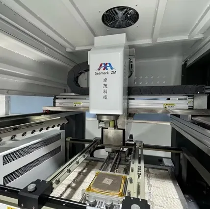
A removable lid may provide access while leaving the grounded frame in place. Follow the intended release mechanism and avoid bending contacts or levering against PCB components. Inspect the opened frame for deformation and loose fragments before moving to BGA work.
A soldered shield requires its own removal process. Its attachment may draw heat into a ground plane, and the shield perimeter can require a different heating distribution from the BGA beneath it. Do not assume that the target chip's recipe is suitable for releasing the shield.
Determine whether neighboring devices will see a significant thermal cycle during shield removal. The subsequent BGA removal and installation add further exposures, so consider the sequence cumulatively. Material handling and moisture preparation may need to cover the whole heated region.
Support the assembly so shield lifting does not flex the board. Confirm release before applying controlled lift; resistance can indicate remaining solder or mechanical retention. Twisting a partly attached shield risks pulling its pads or disturbing small parts close to the seam.
Clean and inspect after shield removal. Check the frame lands, adjacent passives and the intended BGA access path. A shield can come away successfully while leaving a solder fragment that later creates a short, so do not proceed directly from lift-off to the next heating cycle without a checkpoint.
Check the entire motion envelope of the head, nozzle, pickup and alignment system. A nozzle may fit over the chip at one height but collide with a remaining frame during descent. Optical viewing and vacuum pickup can have separate clearance requirements.
Measure the available space around the package, the frame height and nearby connector positions. Review the underside as well: components or fixtures may restrict bottom heating and support placement. Check that thermocouple wires can be routed without interfering with motion.
Feature to review | Possible obstruction | Required decision |
Remaining shield frame | Nozzle or camera path | Retain, remove or change tooling |
Tall connector | Head movement or airflow | Revise access and protection |
Underside components | Preheater gap and supports | Use a suitable fixture |
Shield attachment lands | Cleaning and refitting access | Plan restoration before removal |
A smaller nozzle is not automatically the solution. It changes heat delivery and may leave part of the array inadequately heated. Any tooling change must be checked through the actual thermal response and mechanical clearance.
When comparing BGA equipment, use the complete board or a representative fixture during evaluation. Package-size compatibility on a specification sheet does not establish that the machine can reach a chip inside the remaining shield structure.
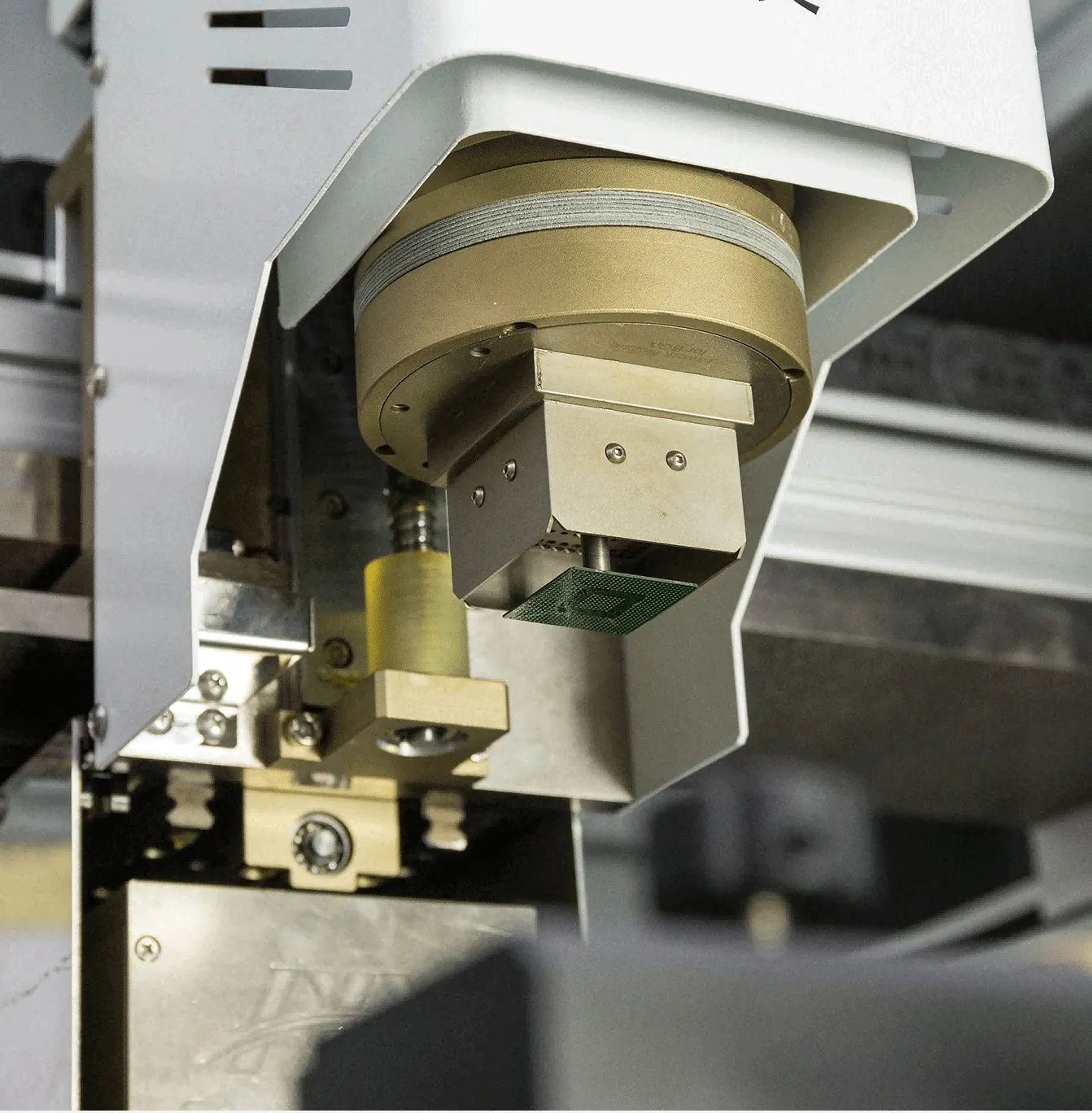
Metal shielding changes local heat paths. It can spread energy away from the target, block airflow or expose another region through conduction. An opened assembly may therefore need a different profile from a board with its cover and frame intact.
During profile development, place temperature sensors at representative target joints and heat-sensitive neighboring components. Pay attention to plastic connectors, contact springs, adhesives and small components beside the frame. The temperature at the target does not establish their exposure.
Protective barriers require validation. Their size, location and attachment can alter airflow, reflect energy or obstruct the head. Insulating one component may shift a hot region elsewhere. Record the installed protection as part of the approved setup rather than treating it as an informal operator preference.
Do not rely on a shield as a heat spreader unless its thermal effect has been evaluated for the actual setup. Leaving a lid in place can conceal the true condition of the BGA and interfere with both measurement and controlled lifting. A process intended to work through a shield needs direct evidence that it meets the relevant thermal and mechanical requirements.
Inspect heat-sensitive neighbors after development trials, including the underside of the board. Visible distortion, displaced parts or changed connector retention are reasons to reassess the process even if the BGA passes its initial electrical test.
Refitting restores a functional part of the product. Check the lid, frame, clips and grounding surfaces for damage or contamination. A distorted lid that appears closed may not reproduce the original contact or retention condition.
For soldered shields, control solder application and inspect the seam according to the product requirements. Avoid loose solder particles, bridges to adjacent features and unassessed additional heating of the repaired BGA. Reinstallation should have its own defined process rather than rely on improvised touch-up.
Perform the BGA inspection before access is closed where practical. Record alignment, relevant hidden-joint inspection and electrical results, then inspect the shield after refitting. Some checks become difficult or impossible once the enclosure is restored.
The final verification depends on product function. RF assemblies may need applicable RF performance or shielding checks in addition to a basic power-on test. A successful boot does not establish that grounding, emissions behavior or receiver performance remains acceptable.
When specifying a rework system, discuss the shield opening and restoration steps as well as chip replacement. The useful demonstration is the complete controlled route, with defined inspection points and a finished assembly that meets the product's requirements.
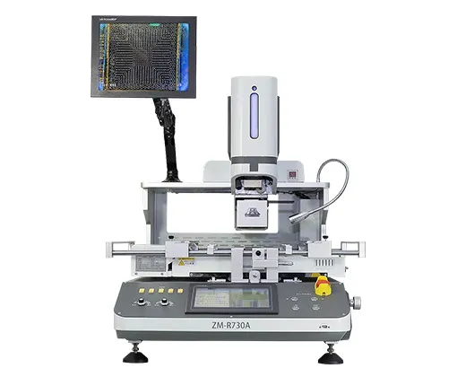
Not always. A removable lid may provide enough access, but the remaining frame must allow nozzle travel, alignment, pickup and inspection. Confirm this on the actual setup.
Only if the process has been evaluated in that configuration. The shield can also redirect heat and obscure the target, so its protective effect should not be assumed.
It may need review. Removing or retaining metal changes the thermal configuration, and each approved profile should identify the shield condition used during development.
Not necessarily. Verify the repaired interconnects and the shield's retention and grounding, then perform the functional or RF checks required by the product.
Plan shielded-board rework from initial access to final restoration. Check the mechanical envelope, validate heating with the intended frame and protection in place, and inspect before closing the shield. The equipment is suitable only when it supports that complete process.
· IPC-7711C/7721C: Rework, Modification and Repair of Electronic Assemblies (Table of Contents)
 EN
 es
 ko
 de
 it
 pt
 th
 ar
 pl
 vi
 tr
 ru