
BGA soldering temperature on a heavy copper PCB should be evaluated using measurements at the joints and heat-sensitive components, rather than a universal top-heater setting. Thick copper layers, large planes and dense via connections can carry heat away from parts of the array while other regions heat more quickly. The challenge is obtaining the required soldering conditions across the array without overstressing the package or neighboring parts.
A workable process begins with the board's thermal layout and measured response. Raising heater settings to increase the BGA soldering temperature without locating the cold region can increase damage risk while leaving the underlying imbalance unresolved.
Copper affects both heat capacity and heat conduction. More copper requires additional energy to raise its temperature, while connected planes spread energy away from the locally heated area. The outcome depends on layer distribution and interconnections as well as nominal copper thickness.
Two boards of similar size can therefore respond differently. One may connect BGA power lands to substantial internal planes through many vias; another may use a different stackup and copper distribution. Their external appearance and package designation do not establish that they can share a rework recipe.
The effect is also time-dependent. A plane may initially draw heat away from the site, then become a source of retained heat during later stages. Starting a second trial before the board returns to the defined initial condition can make a weak recipe appear adequate.
Review the stackup, copper weight, plane coverage, thermal vias and component layout before profiling. When detailed design data is unavailable, use a representative instrumented board to characterize the response and record that limitation. A successful result on a thinner demonstration PCB does not validate the process for a copper-rich production assembly.
The alloy and package limits still apply. Heavy copper changes the energy delivery needed to reach the process window; it does not automatically permit a higher package-body temperature or a different solder alloy requirement.
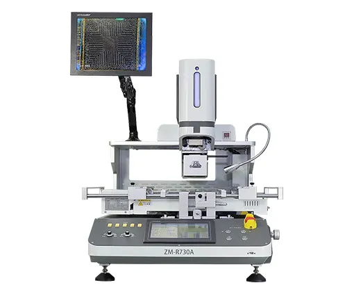
A joint connected to a large copper feature can heat more slowly than one with a lighter thermal connection. If the process is approved using only a hot outer joint or the package-top reading, a lagging region may not receive the intended soldering exposure.
This creates several possible outcomes: incomplete reflow, poor wetting, or a joint whose formation differs from the rest of the array. The visible behavior of exposed solder nearby is useful context, but it cannot prove that hidden joints beside an internal plane have followed the same temperature history.
Place development sensors at plausible thermal extremes. Compare regions near major power and ground connections with less heavily connected areas, while also monitoring the package body. Do not assume that the physical center is always the coldest point; the board's copper network may shift that location.
Observation | Possible explanation | What to check next |
One array region heats slowly | Strong thermal connection to a plane | Joint-level measurements and layout |
Package top heats rapidly | Top energy arrives before the board is ready | Preheat distribution and nozzle conditions |
Repeat run heats faster | Residual board heat | Defined initial temperature |
Nearby connector approaches its limit | Broad heat spread or airflow | Local exposure and protection method |
Treat an electrical failure after rework as a diagnostic problem, not automatic proof of a cold joint. Alignment, contamination, package warpage and damaged lands can create similar symptoms. Use inspection and appropriate electrical testing to narrow the cause.
Preheating can reduce the thermal difference between the board and the locally heated package. By supplying energy to a broader area, it may reduce the burden placed on the top heater. The useful question is how the combined heat sources affect the measured extremes, rather than which heater has the higher setting.
Increasing top heat alone can drive the package surface or nearby exposed features toward their limits before the most thermally connected joints are ready. A longer dwell is not automatically safer: it can increase cumulative exposure and heat components outside the intended repair area.
Develop bottom and top heating together. Check the preheater footprint, underside clearance, airflow and support locations. A fixture that blocks part of the underside can create a new cold region; a support contacting a component can introduce mechanical and thermal problems.
Preheating also has constraints. Broad heating exposes more of the assembly, including underside parts and moisture-sensitive packages. Review their handling and temperature limits before extending the preheat stage. The goal is a balanced assembly response, not the highest achievable board temperature.
When selecting a BGA soldering station, assess usable board coverage, access for external sensors and control of the relevant heating zones. Nameplate power does not demonstrate that a particular heavy copper assembly can be processed within its limits.

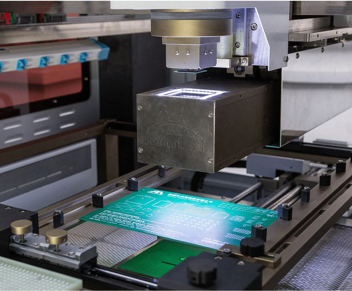
The coldest relevant joint helps determine whether the array receives adequate thermal exposure. At the same time, the hottest package or neighboring location limits how much energy can be added. Approving one extreme without reviewing the other leaves the process window undefined.
For installation, evaluate the solder material's required reflow conditions together with package and assembly instructions. For removal, establish that the joints have released before lifting. The same alloy can appear in both operations, but flux, solder volume and mechanical actions differ, so each process requires appropriate validation.
Use measured curves to examine peak, duration and the complete heating and cooling sequence. A peak reached for an unsuitable interval is not equivalent to the intended process. Avoid substituting a nozzle air temperature for a joint measurement when documenting compliance with the soldering requirements.
A practical development sequence is to measure the existing imbalance, adjust heat distribution, and repeat from a controlled starting condition. Change one meaningful variable at a time where possible. Record whether a change improves the cold joint, worsens the hot location or merely shifts the problem elsewhere.
Define the BGA rework temperature requirements within a validated recipe for the specific board, package and setup. Copying a temperature from another repair bench omits the physical configuration that made that value meaningful.
Identify the assembly's vulnerable neighbors before finalizing the recipe. Connectors, plastic housings, electrolytic components, adhesives and previously reworked devices may have relevant exposure restrictions. The limiting item may sit beneath the board or outside the immediate nozzle outline.
Use shielding only as part of a measured setup. A barrier can reduce direct exposure in one region while changing airflow or reflecting energy into another. It can also obstruct inspection and become a source of electrical contact if improperly positioned. Record the material and placement and verify the resulting temperatures.
Keep the board supported without forcing it flat against an unsuitable fixture. Differential heating and restraint can contribute to distortion, so inspect flatness and component seating before and after development trials. Do not correct an unacceptable thermal result by increasing clamping force without reviewing its mechanical effect.
An evaluation of BGA rework equipment should include the complete assembly, not only the target package. Request a representative trial with the actual fixture, intended shielding and relevant neighboring sensors, followed by the inspection and testing needed for the product.

No. It can require a different energy-delivery strategy to reach the appropriate process window. The allowable peak remains governed by the materials and components being processed.
No. Copper connectivity, vias, airflow and heating geometry can move the cold region. Determine it through layout review and representative measurements.
Not automatically. Extra time may increase exposure without resolving the temperature difference. Compare measured results and component limits before approving that change.
Only within an established validated scope. Changes to copper distribution, stackup, fixtures or surrounding components can change the thermal response even when the package is identical.
Control BGA soldering temperature on heavy copper PCBs by balancing energy delivery across the board and package. Verify the coldest joint while protecting the hottest sensitive location, and keep the full setup consistent. A measured process window is more useful than a universal heater setting.
· NASA / Jet Propulsion Laboratory: NASA Guidelines for BGA and DSBGA Selection and Application
· NIST: Thermocouples Calibration Services
 EN
 es
 ko
 de
 it
 pt
 th
 ar
 pl
 vi
 tr
 ru