
BGA repair on an underfilled assembly is feasible only when the adhesive, package and PCB can tolerate an established removal process. Melting the solder does not release a package that is still bonded to the board. Applying more lifting force can therefore turn a replaceable component fault into damaged lands, broken traces or laminate separation.
For BGA chip rework, the first decision is whether the board, the chip, or both must survive. That distinction changes the acceptable removal method and the value of a trial. Before scheduling BGA repair, identify the adhesive system, review the assembly history and define how the repaired board will be inspected and tested.
Sometimes they can, but survival should never be assumed from a successful lift. An underfilled chip may suffer package cracking, substrate damage or internal separation during removal even when its external surfaces look intact. Recovering a reusable device is a different objective from removing a defective device while preserving the board.
Start with a confirmed fault diagnosis. A symptom near a BGA does not prove that its solder joints are responsible. Compare electrical measurements, inspection findings and the product's failure history before exposing the assembly to another thermal cycle. Reflowing an underfilled package without understanding the fault may hide an intermittent symptom without correcting its cause.
Next, establish the boundaries of the job. Obtain the component identity, package limitations, board construction and available records of previous rework. If chip reuse is required, the plan must include package cleaning, land inspection and electrical evaluation after removal. If destructive component removal is acceptable, protect the PCB rather than trying to preserve a device already designated for disposal.
A representative scrap assembly can help assess feasibility before a valuable board is committed. It should match the adhesive, package and PCB sufficiently closely to reveal relevant risks. A trial on an unfilled board does not validate an underfill removal process.
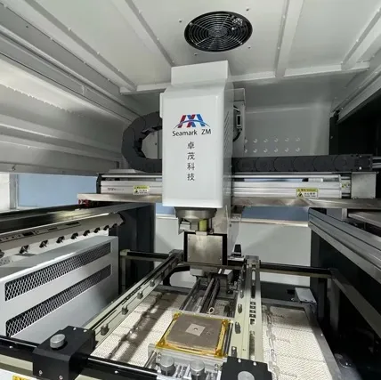
“Reworkable” describes a material's intended processing behavior under specified conditions. It does not mean the cured adhesive can be removed at any convenient temperature. Obtain the material's identification, cure history and supplier instructions, including any restrictions on heat, cleaning agents and residue removal.
Permanent encapsulation can bond strongly enough that an ordinary thermal lift is unsuitable. Specialized removal may be possible, but it requires a separately assessed process and may sacrifice the component. Where material identity is unknown, treat the uncertainty as an engineering decision rather than assuming that a visually similar adhesive behaves like a familiar product.
Also distinguish board-level underfill from material inside the package. Flip-chip underfill between a die and its package substrate is not the same adhesive interface as underfill between the finished BGA and the PCB. A package description mentioning underfill does not establish whether the board attachment itself is bonded.
Material evidence | What it establishes | Practical implication |
Identified reworkable product and cure | A documented starting process | Validate it on the actual assembly |
Identified permanent encapsulant | Routine thermal removal may be unsuitable | Assess specialist removal or replacement |
Unknown adhesive or mixed residues | Behavior remains uncertain | Investigate before heating or lifting |
Solvents require the same discipline as heat. A cleaner that removes flux may not soften cured underfill, while an aggressive chemical may affect solder mask, labels, plastics or coatings. Use only a process whose material compatibility has been checked; visible surface softening alone does not prove that the bonded interface has released.
Full underfill occupies the gap beneath much of the package and surrounds the interconnects. Corner bonding or edge bonding uses more localized adhesive features. These arrangements create different access conditions and different paths for mechanical load during removal.
Localized bonding may leave accessible gaps, but it is not automatically easy to rework. A corner deposit can extend beneath outer rows, and a perimeter fillet does not reveal how far material has flowed internally. Inspect all accessible edges under magnification and compare them with the assembly drawing or process record. Do not classify adhesive coverage from one visible corner.
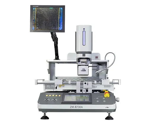
Clearance also matters. Nearby capacitors, shields or connectors may prevent a tool from reaching the adhesive without contacting another part. Record these obstructions before choosing the nozzle, pickup tool and board support. The BGA rework equipment should provide the required access and thermal control, but equipment capability does not establish adhesive removability.
Adhesive removal and solder release must be treated as separate conditions. Releasing an edge bond does not prove every solder joint is molten; conversely, molten joints do not prove full underfill has released. The lift decision needs evidence for both interfaces.

The most serious damage often results from force applied before the assembly is ready to separate. Prying transfers load through the package into lands and traces. Scraping across a bonded surface can cut solder mask or detach small copper features, especially where heat has reduced the board material's resistance to mechanical stress.
Support the PCB so that removal does not bend it around the package. Verify the actual thermal response with an established profile, and use controlled vertical pickup only within the approved process. If the package resists the expected release, stop and reassess. Increasing vacuum, twisting the head or levering a corner is not a substitute for identifying the remaining attachment.
After removal, inspect the site before cleaning aggressively. Record lifted or missing lands, exposed fibers, damaged mask, broken traces and suspicious discoloration. Residual adhesive can conceal damage, so inspection may need to be repeated as cleaning progresses. Protect neighboring components from fragments and cleaning residues.
Use the PCB land pattern and package ball map together to distinguish a damaged land from an intentionally absent feature. A damaged land assigned to a no-connect position may have different electrical consequences from a torn signal land, but both require assessment against the board design and repair criteria. Continuity testing can help assess connected nets, but it cannot by itself prove that a partly detached land will remain mechanically reliable.
Board replacement is often the better option when adhesive identity is unavailable, critical lands are already compromised, or the available inspection cannot establish an acceptable result. A replacement decision should account for the required reliability and the consequences of an intermittent return failure.
Compare the complete routes. Repair includes diagnosis, process development, removal, site restoration, component replacement and verification. Replacement includes availability, configuration, firmware or calibration transfer, and final system testing. The lower component purchase price does not necessarily identify the lower total cost.
For component rework and board repair, define stop conditions before the job starts. Examples include unexpected resistance during release, new laminate damage, loss of a critical land, or a requirement for repairs beyond the approved capability. A documented stop point helps prevent repeated heating from becoming an uncontrolled attempt to recover a deteriorating board.
When assessing a rework system, ask for a demonstration using a representative assembly and the intended inspection route. A successful demonstration on an accessible, unfilled BGA does not answer whether your bonded assembly can be repaired. The relevant result is a board that meets the agreed electrical, physical and reliability requirements after the whole process.
Not reliably. Higher temperature may soften some materials, but it also increases exposure of the package and PCB. Material identification and a validated process are needed before changing the thermal cycle.
No. Corner bonding describes adhesive placement, not the electrical condition or recoverability of the chip. Reuse requires an acceptable removal process and subsequent package and functional checks.
Follow the product's approved assembly requirements. Omitting a specified reinforcement can change mechanical behavior, while adding an unqualified adhesive can introduce new stresses and complicate future repair.
No single inspection proves that. X-ray can reveal relevant hidden interconnect defects, but laminate, package and electrical concerns may require other inspections or tests appropriate to the product.
Underfilled BGA repair starts with identifying what holds the package to the board and deciding which parts must survive. Establish adhesive compatibility, access, solder release conditions and inspection criteria before removal. When the process cannot protect critical lands or verify the finished assembly, board replacement is a defensible engineering choice.
· NASA NEPP: BGA Underfill for COTS Ruggedization
· IPC-7711C/7721C: Rework, Modification and Repair of Electronic Assemblies (Table of Contents)
 EN
 es
 ko
 de
 it
 pt
 th
 ar
 pl
 vi
 tr
 ru