
A BGA rework machine should lift a package only after the solder joints have released and the pickup tool has established a stable grip. Package slip and premature lifting are different problems: one concerns holding the component, while the other concerns separating it from the board. Increasing vacuum does not make solid solder or cured adhesive release safely.
Repair teams should therefore qualify pickup as a sequence that includes tool selection, surface contact, vacuum confirmation, release detection and controlled motion. This approach makes troubleshooting more useful than treating every dropped or damaged component as a pump problem.
A vacuum tool depends on a pressure difference over an effective sealed area. In a simplified static model, holding force is approximately pressure difference multiplied by that area. Real pickup performance also depends on leaks, surface shape, tool compliance and motion. The pump's rated vacuum is not necessarily the pressure available at the package while air leaks around the contact.
Common causes of slip include an off-center pickup point, a damaged seal, contamination, a blocked line or an uneven surface that prevents stable contact. A package may appear secure while stationary and rotate when the head accelerates. That behavior points toward grip geometry or dynamic loading, even if the displayed vacuum looks normal.
When qualifying a BGA rework machine, observe the whole pickup sequence with representative components. Record when the movement begins: during initial separation, after the package clears the board, or during transfer. Each location suggests a different cause and prevents unnecessary adjustment of the heating profile.
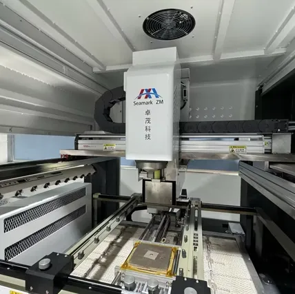
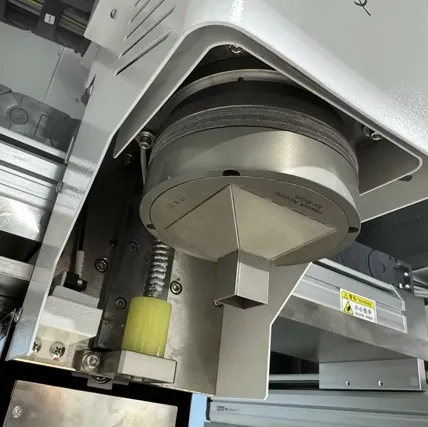
Choose a tool that contacts a mechanically suitable part of the package without fouling nearby features. Lids, exposed dies, steps, printed markings and residue can change the available contact area. A tool that works on a flat molded package may be unsuitable for a package with a small raised lid. Follow the component and equipment guidance rather than assuming that the largest tool always gives the safest grip.
Check both the contact face and the approach path. A larger cup may seal well but collide with the heating nozzle or neighboring components. A compliant material may accommodate small irregularities, yet its temperature rating and contamination behavior must match the operation. Do not improvise contact on a fragile exposed die when the package has no approved pickup location.
Verify the seal on a suitable unpowered sample before a live removal trial, then assess it under representative process conditions. Heat can change seal compliance and surface contamination. Inspect consumable tools regularly for hardening, cuts and deformation, and include their identification in the recipe so an apparently minor nozzle substitution does not go unnoticed.
Use enough vacuum to retain the package throughout the qualified motion, within the tool and component limits. There is no universal vacuum pressure setting for all BGAs because package weight, effective sealed area and pickup-tool design differ. Establish the minimum acceptable pickup indication and the machine response to a failed or interrupted seal using the equipment's supported controls.
Pressure and airflow are related but different. A restriction can make a reading upstream of the tool look satisfactory while the grip develops too slowly. A leak can require substantial flow and still prevent the desired pressure difference. Check measurement location, tubing connections, filters and pump performance before blaming the component surface.
For a BGA desoldering machine, confirm how vacuum timing interacts with removal motion. Some sequences establish contact before reflow; others use a different controlled approach. The approved sequence must prevent the head from pressing on the package or applying unvalidated upward force while solder remains attached. An alarm is useful only if it occurs early enough to prevent a drop or uncontrolled lift.
The heater display does not establish that every hidden joint has reached the condition needed for removal. Board copper, shielding, package size and bottom heating affect the temperature distribution. A visible edge joint can release while other parts of the array remain attached. Likewise, elapsed time alone is not a reliable release signal across different assemblies.
Develop a representative removal profile using suitable temperature measurements and the component, alloy and board constraints. Where a machine offers force-controlled or release-detection features, validate what they detect and how the limits are set. Do not assume that the presence of vacuum proves the component is free: vacuum measures a grip condition, not joint separation.
Adhesive and underfill introduce an additional restraint. If the package resists the validated lift sequence, stop and investigate rather than increasing pull force or rocking it sideways. Premature movement can tear pads or damage the laminate even when the package itself remains intact. Any exploratory reflow also belongs in the thermal history; repeating it without diagnosis consumes process margin.
Observation | First check | Avoid |
Package stays on the board | Joint release and adhesive restraint | Increasing pull force blindly |
Package lifts then rotates | Seal position and motion acceleration | Assuming heat is always the cause |
Vacuum falls during transfer | Leaks, tubing and seal condition | Continuing over valuable assemblies |
Package does not release at placement | Release command and tool adhesion | Dragging the tool across the part |
After separation, clear the surrounding features vertically before moving laterally. Qualify the transfer height and path with the actual board layout, heating nozzle and receiving fixture. Keep acceleration and deceleration within the demonstrated grip capability. A package that survives a gentle manual transfer may slip during the faster automatic cycle.
The receiving surface also needs definition. A removed hot component may require a compatible support or tray that avoids damage and preserves orientation. During installation, verify alignment and controlled touchdown before releasing vacuum. Residue or an unsuitable contact face can make the package stick to the pickup tool even after vacuum is disabled.
If a package slips, pause the sequence and inspect the board and component before resuming. Check for displaced nearby parts, disturbed solder and contact damage. Recalibrate alignment where the event could have shifted the tool or fixture. When evaluating a BGA repair machine, assess its response to a pickup fault as well as its nominal placement accuracy.
A useful recovery instruction defines whether the component can be repositioned, whether another thermal cycle is allowed and who can approve the decision. Preserve fault logs and sample photographs. Repeated drops at one motion step can otherwise disappear into individual operator notes, leaving a systematic setup problem unresolved.
For example, a package that separates vertically without resistance but rotates during the first sideways move presents a different problem from one that never leaves the board. In the first case, examine the contact center, seal stability and acceleration. In the second, confirm joint release and possible adhesive restraint before revisiting grip settings. Keeping these observations separate reduces the chance of applying a stronger lift to an unreleased component.
A useful daily setup check can use an approved representative sample to confirm tool condition, seal indication and the transfer path before valuable boards are loaded. Define the check through the equipment procedure and local qualification. It should detect a changed setup without adding unnecessary heating or handling to the repair unit itself.
No. Vacuum holds the component; it should not be used to tear the component from joints that remain attached. Investigate the profile, joint release and adhesive condition before applying another lift attempt.
That depends on the equipment's validated sequence. Early contact can be part of an approved process, but its contact force, tool temperature resistance and lift timing must be controlled. Copying another machine's sequence without validation is unreliable.
Temperature can change seal compliance, contamination behavior and contact stability. Compare the cold and hot conditions, then examine motion settings. A cold holding test establishes a useful baseline but cannot qualify the complete removal process.
No. Pickup only demonstrates one handling event. Inspect the site and complete the required joint, electrical and functional checks after the repair. A secure lift does not exclude damage caused before separation.
Stable vacuum pickup requires a suitable contact tool, a verified grip, confirmed package release and controlled transfer. Keep grip faults separate from heating or adhesive restraints during diagnosis. Qualify the full sequence on representative assemblies and make recovery decisions explicit so a small handling error does not become repeated board damage.
· NASA Glenn Research Center: Component-Level Electronic-Assembly Repair (CLEAR) Operational Concept
· NASA / Jet Propulsion Laboratory: NASA Guidelines for BGA and DSBGA Selection and Application
 EN
 es
 ko
 de
 it
 pt
 th
 ar
 pl
 vi
 tr
 ru