
BGA rework systems can restore a component's attachment, but a repaired assembly needs evidence of both acceptable workmanship and required operation before release. A passing X-ray image shows that the inspected structure meets the selected imaging criteria. It does not demonstrate that the semiconductor works, every connection carries the intended signal or the original intermittent fault has disappeared.
Post-rework testing should therefore connect the repair to the assembly's functional requirements. Plan the evidence before removal, preserve the original fault description and define how the team will resolve conflicting results. This avoids the common mistake of using whichever test happens to pass as the release decision.
Yes. X-ray inspection can reveal structural defects within its detection capability, including many solder bridges and gross placement errors, and can characterize selected void and joint features. Detectability depends on resolution, viewing angle, overlapping structures and the defect itself. Some cracks and interface defects may be difficult to distinguish in a particular image, even when the ball pattern appears regular.
Electrical and functional failures also extend beyond solder geometry. A damaged die, incompatible component, missing configuration or unstable power supply can produce a non-working board with acceptable-looking joints. Structural inspection cannot establish semiconductor behavior simply because the repaired component occupies the correct position.
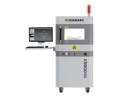
Use a BGA inspection system with a defined inspection plan: identify the package, image views, acceptance criteria and limits of detection. Where the concern requires additional angles or CT, determine whether those methods add relevant evidence. Higher imaging capability still does not replace a test of the required function.
Separate basic electrical screening from functional verification. Unpowered checks can identify selected shorts or abnormal conditions before power is applied. Controlled power-up can check expected rails and current behavior. In-circuit or boundary-scan testing may exercise accessible connections, but coverage depends on the board design and available access.
Functional tests should exercise the operations associated with the replaced or reballed component. A processor-based board may need memory activity, communication interfaces, storage access and relevant power states, rather than a single successful boot. Match the test to the circuit: a high-speed link operating briefly at a reduced rate does not demonstrate performance at its required rate.
Build a coverage matrix that connects important requirements to tests and records remaining gaps. A “100% tested” statement is meaningful only when its coverage is explicitly defined and supported by the test plan. Counting test steps is not the same as demonstrating coverage of every pin or failure mechanism.
Test category | Useful evidence | Important limit |
Structural inspection | Observable joint and placement condition | Does not prove chip operation |
Unpowered electrical checks | Selected shorts and accessible network conditions | May miss load-dependent faults |
Functional testing | Required behavior in exercised modes | Unused functions remain unverified |
Temperature or load testing | Behavior under approved operating conditions | Must suit the product and failure concern |
A BGA rework machine and a test station serve different roles. Coordinate them through the board identity and job record so an acceptable process trace can be compared with the correct test results. Do not assume machine completion means assembly acceptance.
A board can pass at room temperature and fail after warming, changing load or entering a different operating mode. The repair plan should reproduce the original complaint under controlled, permitted conditions where practical. Record ambient conditions, relevant component temperatures, software version, load and the time at which the symptom appears.
Temperature-dependent behavior does not automatically prove a cracked BGA joint. Semiconductor characteristics, power regulation, connectors and software can also change with operating conditions. Correlate the symptom with measurements instead of applying more heat to the suspected package whenever the fault recurs.
Use approved thermal or load tests suited to the product. These are not interchangeable with destructive accelerated reliability experiments. Avoid arbitrary extremes or board flexing that could introduce new damage. If the available test cannot reproduce the field environment, state the gap and decide whether additional investigation is needed before release.
Capture errors while the condition is present. A test that checks only after cooling may miss a transient event. Where appropriate, log counters, communication errors, rail measurements or accessible continuity signals with enough timing information to relate them to the symptom. Distinguish expected parameter changes with temperature from actual violations of the requirements.
Traceability makes the evidence usable. Link the board serial number, revision, component identity and reported fault to the removal and installation records. Include the recipe version, relevant measurements, material identity and deviations. Then associate the inspection images and final test results with that same job.
Retain actual values where they matter, rather than only a green status indicator. A parameter close to its limit may still pass while showing a meaningful change from the baseline or known-good comparison. The test procedure should define how such observations are reviewed; operators should not invent new acceptance limits after seeing the results.
For organizations comparing BGA rework equipment, ask how records are exported and retained alongside external test data. A machine may retain a recipe without recording every detail of the repair. Confirm which information is available automatically and which must be captured in the work instruction.
For returned failures, preserve the previous repair record before starting another operation. This supports electronic component failure analysis by showing whether the same symptom, operating condition or process deviation has recurred. Without that history, the next technician may repeat the original repair without learning why it failed.
Treat disagreement as a diagnostic task. If X-ray passes and a functional test fails, hold the board and investigate electrical, component, configuration and test setup causes. Recheck the image's detection limits if the suspected joint defect was not one it could reliably reveal. A structural pass does not overrule a demonstrated functional failure.
If a functional test passes but structural inspection finds a rejectable defect, investigate that defect against the applicable requirements. The test may not exercise the affected connection, or the present contact may be unstable. Do not waive workmanship criteria simply because an application starts successfully.
A third possibility is that two test stations disagree. Verify fixtures, connections, software, instruments and the test configuration before concluding that the board is intermittent. Repeat testing to resolve a defined question, not until one pass appears. Record the discrepancy and the rationale for its disposition.
Release authority should be explicit. A technician can complete the repair while an engineer or quality representative resolves incomplete coverage or conflicting evidence. If an exception is permitted, preserve its scope and approval. A decision made under a documented limitation should not silently become the default for later assemblies.
For example, a repaired board may boot normally while a high-speed interface reports errors only under sustained traffic. If the original release test exercises neither that interface nor its required rate, its pass does not contradict the observed failure; it simply has a coverage gap. Update the diagnostic plan to measure the interface under controlled conditions, while preserving the previous result and its limited scope.
Maintain test configuration as carefully as the repair recipe. Fixture contact, cable condition and software settings can change the outcome. A known-good reference can help assess the setup, provided it is comparable and its own condition is controlled. This supports useful repeat testing without turning repeated execution into a search for an isolated pass.
No. CT can improve structural visibility for selected defects, but it does not demonstrate required electronic behavior. Its results belong alongside electrical and functional evidence in the acceptance decision.
Only when the approved acceptance requirements establish that this test provides sufficient coverage. Many boards need additional interfaces, operating modes and load conditions exercised. A boot sequence normally covers only part of the assembly's behavior.
Not automatically. Use the product's approved verification requirements and the failure concern to select tests. Qualification experiments and routine release tests have different purposes, and unsuitable exposure can add damage.
Record that limitation and complete the agreed diagnostic and test plan. Do not label the repair as proven solely because no fault appeared during a short test. The disposition should reflect coverage and the consequence of recurrence.
BGA rework systems need a release process that combines workmanship inspection with meaningful electrical and functional verification. Define coverage, exercise relevant conditions, retain traceable results and investigate disagreement. A passing image is useful evidence, but it cannot stand in for demonstrated operation of the repaired assembly.
· NASA / Jet Propulsion Laboratory: 3D X-ray CT for BGA/CGA Workmanship Defect Detection
· NASA Small Spacecraft Systems Virtual Institute: Electronics Functional Testing
 EN
 es
 ko
 de
 it
 pt
 th
 ar
 pl
 vi
 tr
 ru