
A laser reballing machine trial succeeds when it produces consistently attached solder balls without damaging the package, and when the result survives the agreed inspection and electrical checks. A visually attractive ball array is only one part of that decision. Repair teams also need to know how much variation the recipe can tolerate before wetting becomes incomplete or heat exposure becomes unacceptable.
The trial should establish a documented operating window for a specified component or a validated family of components, solder alloy and preparation method. It is not a universal combination of laser power and dwell time. This guide explains how to structure that trial, interpret its results and decide whether the process is ready for routine use.
Start by defining the trial unit. Reballing normally renews the external solder balls of a removed component; it does not repair the silicon or prove that internal package connections remain sound. Confirm the component identity, ball pattern, pad condition and intended alloy before assigning a recipe. Record previous removal and reballing exposure when known, because a previously stressed package is a different starting condition from a new sample.
Agree on acceptance criteria before running the first parts. These should cover ball presence and position, attachment to the pad, coplanarity appropriate to the assembly process, package condition and the available electrical verification. Where later board assembly is part of qualification, include that step: a ball that looks acceptable on the loose component may still create a poor joint after placement.
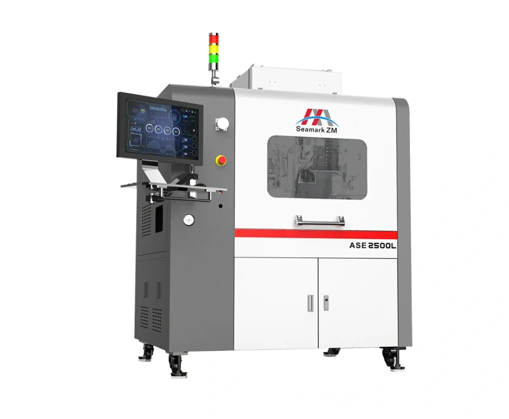
When evaluating a laser reballing machine, request trials on representative parts rather than only on easy demonstration samples. Include the package sizes and thermal masses that will actually enter production. Label every sample and preserve failed parts for comparison; failure boundaries are useful results, not material to discard from the report.
For a continuous beam at constant power, nominal incident energy is power multiplied by exposure time. For a pulsed source, pulse energy, pulse duration and repetition rate also matter. Neither calculation gives the energy absorbed by the solder joint directly. Reflection, wavelength, focus, surface condition and the illuminated area influence how incident energy becomes heat.
Consequently, increasing dwell time is not interchangeable with increasing power. A short, concentrated exposure can produce a different temperature distribution from a longer exposure with the same nominal energy. Ball delivery timing and contact with the pad also affect the outcome. Where the system provides temperature feedback, confirm what surface it measures and whether that measurement represents the attachment site.
Build the first trial around controlled changes. Keep ball diameter, pad preparation, flux or fluxless process, focus position and fixture condition fixed while screening power and dwell. Then investigate interactions with preheat and scan order. Record actual settings and software recipe versions so a promising result can be reproduced after maintenance or a shift change.
Local heating concentrates the heat input, but it does not confine all heat to one ball. Heat conducts into the pad, package substrate, copper structures and fixture. The temperature at a later ball can therefore depend on the order and spacing of earlier exposures. A recipe tested on a few isolated positions may behave differently across a complete array.
Use representative edge, corner and central positions when comparing results. Examine whether the first and last portions of the array differ. Where technically feasible, characterize the package temperature with suitable instrumentation on sacrificial samples. Thermocouple attachment and optical temperature measurements both have limitations; their placement, response and calibration belong in the trial record.
Preheat can change the starting temperature and the local energy required, but it adds to total package exposure. Do not copy a board reflow profile directly into a laser trial. Define limits from component guidance and process evidence, then check the combined effect of preheat, local exposure and cooling. The shortest cycle is useful only if it leaves enough margin for normal variation.
Inspect attachment at useful magnification after the part has cooled sufficiently for handling. Missing balls, obvious misalignment, bridges and inconsistent ball height are immediate reasons to investigate. A spherical appearance by itself does not demonstrate adequate wetting: a ball can retain a rounded shape while attachment to the pad remains incomplete.
For process qualification, combine surface inspection with a suitable attachment evaluation on representative samples. Depending on the package and agreed plan, this may include ball shear or pull testing, sectioning, or subsequent assembly and electrical verification. Record the failure location as well as the force where mechanical testing is used. The method must suit the geometry; an unsupported force threshold copied from another package can mislead.
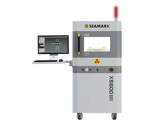
Look separately for package distress, including blistering, discoloration, deformation and pad damage. Absence of these signs does not exclude internal damage. An appropriate BGA inspection system can support selected structural checks, but X-ray images cannot certify every metallurgical interface or demonstrate chip functionality. Escalate unexplained failures rather than compensating indefinitely with more heat.
The usable window is the region in which all agreed criteria pass under representative variation. Its boundaries may come from incomplete attachment at lower heat input, package distress at higher exposure, or unstable results caused by ball delivery and positioning. One successful setting does not establish that region.
Trial result | Likely question to investigate | Release implication |
Incomplete attachment | Energy delivery, pad condition or process chemistry? | Establish the cause before raising exposure |
Good attachment with package distress | Excess local or accumulated heating? | Reject the setting despite attractive balls |
Good average result with scattered failures | Delivery, focus, fixture or material variation? | Resolve repeatability before release |
Repeated passes near several settings | Are all critical criteria and variations covered? | Candidate region for confirmation trials |
After screening, repeat candidate settings on additional representative samples and challenge realistic variation, such as approved ball lots, fixture loading and package starting temperature. Choose a nominal setting with practical margin from observed failures, rather than the fastest setting at a boundary. Do not calculate a capability index from a handful of exploratory runs or treat a pass percentage without sample context as proof of production stability.
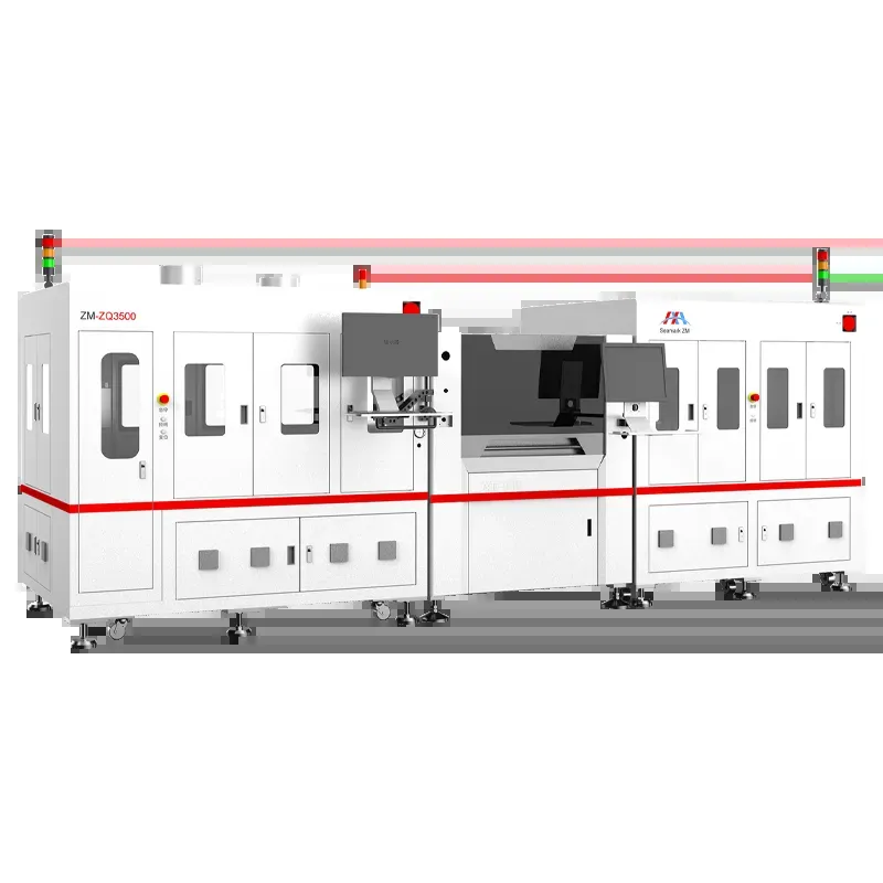
For an automatic BGA reballing machine, automation can repeat commanded settings while incoming parts still vary. When comparing a BGA reballing machine, ask how recipes, alarms, sample identity and inspection results are retained. A usable recipe includes preparation and handling controls alongside the laser settings.
For example, suppose an exploratory trial produces good attachment at a center setting but inconsistent attachment after a small reduction in dwell. The next decision is not to declare the center setting qualified. Repeat the comparison, inspect preparation and determine whether the apparent boundary is stable. Then challenge the higher-exposure side without exceeding documented material limits.
Record changes between trial sessions, including optics cleaning, fixture replacement and calibration work. If the same commanded setting produces a different result afterward, compare the physical setup before changing the recipe. The process window belongs to a defined equipment and material condition; it is not detached from the condition in which it was demonstrated.
No. Package construction, pad finish, solder alloy, ball diameter and fixture contact can change the heating response. Grouping similar parts is reasonable only after trials show that the proposed family shares an acceptable operating window.
No. Incomplete wetting may originate in contamination, oxidation, poor contact or unsuitable chemistry. Additional power can increase damage while leaving the original problem unresolved. Review preparation and delivery evidence before changing exposure.
There is no sample count that proves every application. Define the sampling plan around the consequences of failure, expected variation and required confidence. Separate exploratory screening from confirmation and longer-term monitoring; a few demonstration parts belong to the first stage.
Where accessible and appropriate, yes. A baseline helps distinguish pre-existing component failure from damage introduced during processing. State which functions or connections were actually checked; limited access to a loose package may leave important uncertainty.
A laser reballing machine trial should connect programmed settings to measured outcomes and establish the boundaries of acceptable performance. Control the incoming condition, examine heat accumulation across the array, verify attachment and package integrity, and confirm a region with repeatable margin. Approve a complete process for defined parts rather than a power setting presented without preparation, inspection or test evidence.
· NASA / Jet Propulsion Laboratory: NASA Guidelines for BGA and DSBGA Selection and Application
· IPC / Global Electronics Association: Effects of BGA Rework Cycles on PCB Assembly Reliability
 EN
 es
 ko
 de
 it
 pt
 th
 ar
 pl
 vi
 tr
 ru